 |
|
 |
This article is copyright © 2006 by Audio Amateur Corporation. PO Box 876, Peterborough, NH 03458, USA. All rights reserved.
“Sometimes they come back…again” was the title of a 1996 horror movie: in this article there’s nothing scaring, but just an old reflex variation that reappears."
Auri is a floor standing two way speaker, that uses the unusual Double Chamber Reflex (DCR) enclosure which helped a lot in reducing the standing wave creation, typical of the tower speakers. All measurements were done using Speaker Workshop, excluding the in room response, and all the SPL values are not absolute.
The drivers
My intention was to use a ribbon tweeter since I like to experiment uncommon drivers, knowing their sound as rich of details but with a limited vertical dispersion. About the vertical dispersion issue, for some people (mainly the ribbon drivers resellers) it is a positive feature since makes the driver less dependent of the listening room; on the other side some people assures that using ribbons create only one narrow listen point, making difficult group listening. My thought is that room reflections and reverberations have a big role, explaining why the same speaker might sound well in a room but better in another: one of the advantage of building a speaker is that you can fine tune it, through the crossover, for your listening room. But back to my tweeter choice, I ended up with the ATD DDRT120 that is identical to the Silver Flute YAG20-1: unfortunately, for my wallet, the price paid for the ATD in Italy is very different from the Silver Flute sold in the USA! It often happens that in my country cheap drivers become Hi-end (in price) ones. Anyway, in a two way system it is important to use a tweeter with a low resonance frequency since its crossover cut-off frequency should be at least one octave above its Fs: the ATD Fs is at 1100 Hz making it a good choice. The woofer, instead, needs an extended off-axis frequency response: ideally you should use each driver till it works like a rigid piston, that can be easily calculated through the formula F=345/2d where d is the driver effective diameter expressed in meter. However you must take into consideration the cone material, that can make miracles in increasing the driver rigidity, therefore its rigid piston frequency range. In fact the Focal 7K 4412 (my woofer choice), whose cone is made of polykevlar, showed a very good off-axis response allowing a high cut-off frequency; moreover, it has the right Qts for a vented enclosure and a 90 db sensibility. Here’s its measured Thiele and Small parameters:
|
Fs : 44,9 Hz |
Qts : 0,42 |
Qms : 6,99 |
Qes : 0,44 |
|
Re : 6,06 Ohm |
Vas : 37,6 litri |
Sd : 176,7 cm2 |
|
The 7K 4412 frequency response shows a typical rigid cone peak at its break-up frequency, around 2800 Hz; I also measured a dip around 1100 Hz, that wasn’t present in the Focal datasheet. I decided to investigate it, noting that in the woofer free air impedance response there was a peak at that frequency, to confirm the reliability of my measurement; so I contacted the Focal in France asking them how a dip can disappear like magic. They confirmed me that the dip at 1100 Hz really exists but is not visible in the datasheet since their measurement methodology (on infinite baffle) tends to rise up to the cone break-up point, somehow compensating for the dip at that particular frequency; they believe the dip is due to a slight mechanical termination mismatch between the polikevlar cone and the surround.
The cabinet
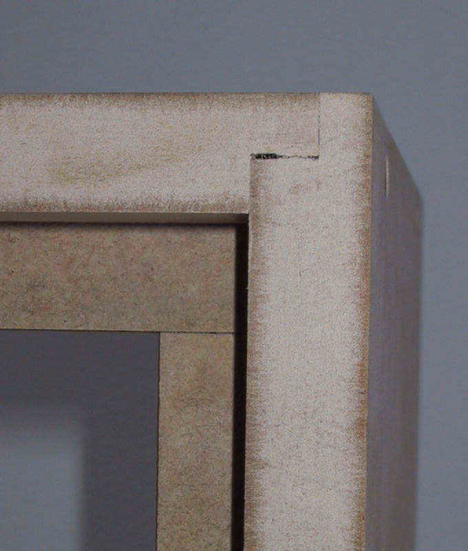
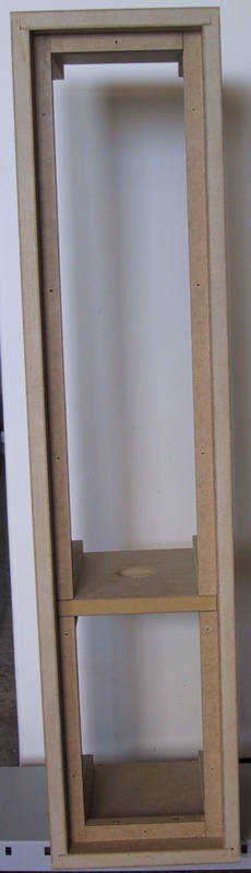
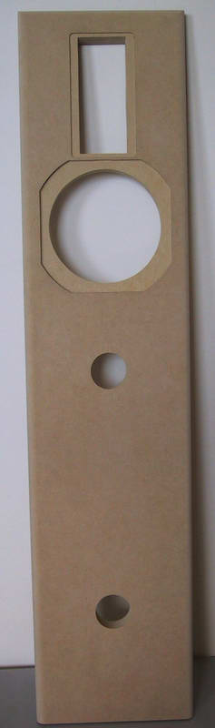
Auri is a tower floor standing speaker with internal dimensions of 959x188x218 mm (HxWxD) therefore well away from the golden ratio: here’s what I’ve done to try to make a deaf cabinet. All panels are 2 cm thick MDF with the exception of the front and rear ones, whose thickness is of 3 cm; an internal frame is present all around the perimeter, which helps to harden the structure and at the same time serve as end guide for the front and rear panels; the top, bottom and lateral panels use L joints:
|
|
|
|
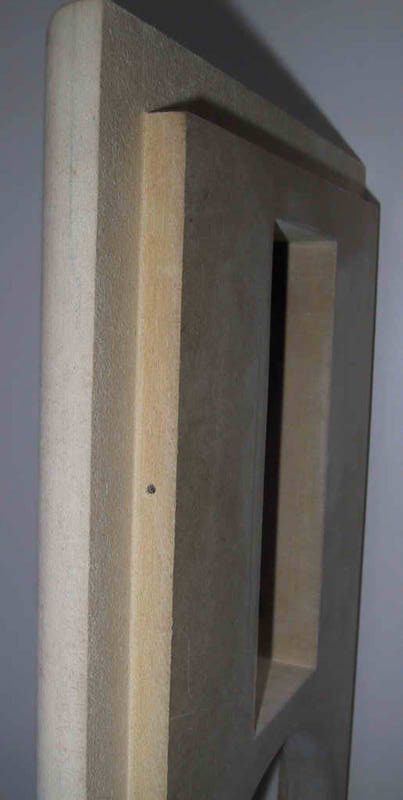
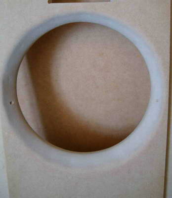
The front panel has a step, so that it partially stuck inside the cabinet, while its edges are rounded to reduce cabinet edge diffraction. Actually exist two schools of thought about how much audible cabinet edge diffraction is: the first school affirms that the change from 4pi str to 2pi str causes an image degradation, and some suggests the use of a compensation circuit; the other school states that the room response compensates for any low frequency pressure drop, noticeable in the anechoic response; moreover the diffraction effects are very directive while, usually, the listening are made off-axis. My opinion is to stay in the middle, thus trying to minimize the diffractions, since eliminating them completely is impossible, by using a narrow front panel that contributes in a better sound image, and by rounding its edges with a radius of at least 1”, as reported by J. D’appolito and J. Moriyasu1. I also flush-mount all the drivers, to reduce diffraction at driver’s edge, and enlarged the woofer internal hole since the panel thickness (3 cm) could have created an unwanted resonance
 |
 |
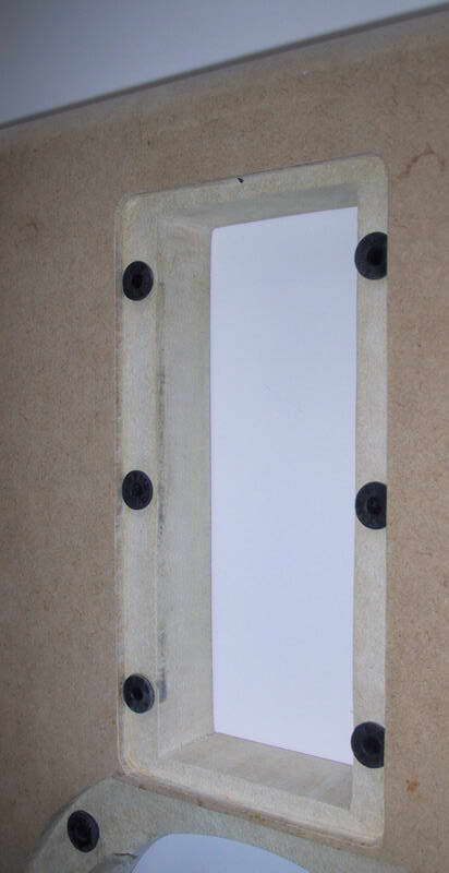
On all panels internal side, excluding the front one, I used a product named Fonogel from AZ Audiocomp: it is a viscous-elastic damping compound, that’s not toxic and doesn’t smell like solvent based products. I also used a damping mat on all panels except the front one, choosing from the long fibre polyester and the rusticated expanded polyurethane: of each type is available a damping factor chart, therefore knowing the cabinet internal dimensions and applying the formula F=345/2d, where d is expressed in meter, I used the better mat type for that particular resonance frequency. Another issue I took care of, is the transmission of vibrations from the woofer to the cabinet and the tweeter: first of all I must say that various modes of panel vibration, or resonance, exist. The first mode is referred to forward-backward panel movement; the second mode is when half panel moves forward while the other half moves backward, divided on the vertical axis; the third mode is like the second one but on the horizontal axis; the fourth mode refers to a panel divided in three sections with the centre section moving forward while the other two move backward; and so on. To reduce the transmission of vibrations from the woofer to the baffle, I used rubber insulated rivet nuts named Well-Nuts or Flex-Loc. Actually it’s not so easy to find speakers that use this kind of nuts, even if Vance Dickason2 suggests its use from a long time and their cost is not an issue. If you are still not convinced in their utility, I suggest you to read an old Audioxpress article from J. Moriyasu3, where it’s proved that using Well-Nuts brought a reduction of second-third-fourth mode vibrations, while the first mode remained the same.
 |
|
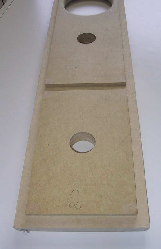 |
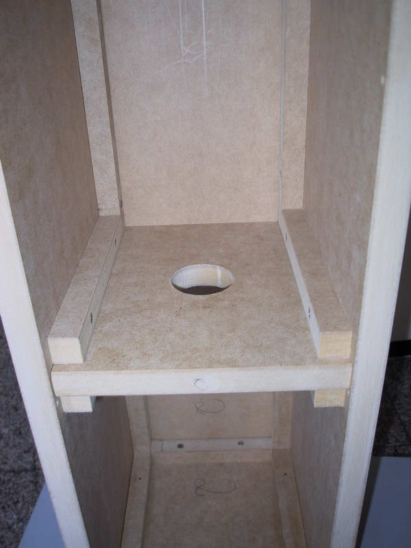
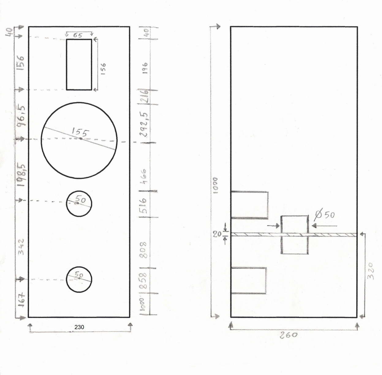
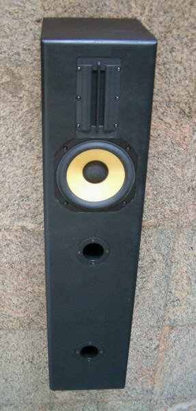
The chambers separation panel is 2 cm thick, with rails on the lateral panels and embedded in the front-back ones; the cabinet is brush painted and the dimensions diagram (expressed in mm) is showed below with the ended speaker.
|
|
 |
The tuning
Auri is tuned at about 37 Hz in a net volume of 34.5 litres, considering both chambers, through three ports (two external and one internal) with 5 cm of diameter and 14.5 cm of length. The chambers volume ratio is 2:1, and has been obtained taking into account the drivers and crossover volumes, both located in the bigger chamber V1.
I spent over six months for the crossover design of Auri, alternating computer simulation to listening and measurement, trying to keep the drivers phase similar, in the drivers crossover region, as well as a dip free off-axis total response. The starting point is depicted by the unfiltered drivers response, where are clearly visible the Focal 1000 Hz and 2800 Hz peaks, and the tweeter 1500 Hz one followed by a dip. With the woofer I used two parallel RLC cells in series with the signal to take care of the peaks, and a II° order filter; actually in the second cell, the one that works on the 1000 peak, I didn’t use any resistor since the measurement appeared more flat without it; the R2 resistor, that is in series with the C3 cap, is used to vary the filter Q. With the tweeter, after the resistor R3 used to align the drivers sensibility, there is a III° order filter; all drivers are connected in phase with the signal, and their crossover frequency is at about 2700 Hz. The used crossover schematic is depicted below:
 |
|
Auri: driver's unfiltered response |
 |
|
Auri: the crossover |
The speaker measurements
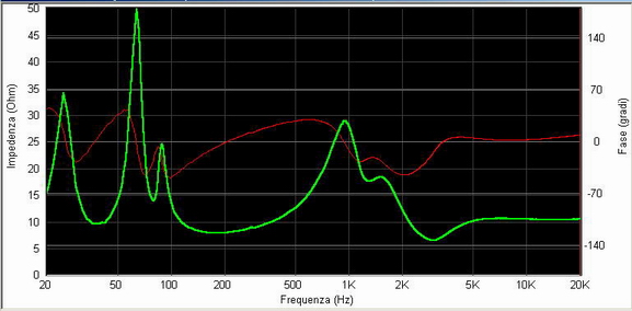
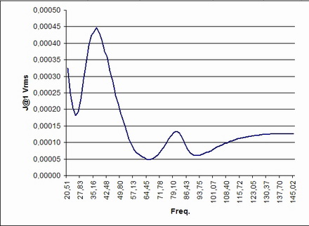
The system impedance response shows the three peaks present in all double tuned loudspeakers; there’s no presence of unwanted resonances and the load offered to the amplifier is of the easy kind, being the module always more than 6 ohm and with a positive argument at its minimum. The impedance is a complex number formed by a real part (the module) and an imaginary one (the argument): with some calculations, useful information can be obtained. Considering only the real part of the impedance and applying the formula Rs=Z*cos(q), it’s possible to know the speaker maximum load value: for example, from the impedance chart I have that Frequency (f)= 41 Hz, Impedance (Z)=9.9 ohm, Phase (q)=+9.5°; converting the phase degree into radiant and applying the said formula gives that Rs=9.9*cos(0.16)=9.7 ohm, thus at 41 Hz it’s as if the amplifier is connected to a 9.7 ohm resistive load. Auri maximum load situation happens at 2819 Hz with a resistive load of 6.2 ohm. You can import your impedance into a spreadsheet like Excel, and let it do the calculation for you. Moreover, considering both the impedance real and imaginary part, you can calculate the energy requested by the speaker at each frequency applying the formula
W=cos(q)/(|Z|*2pf), allowing you a better vision of what the amplifier will have to give: W=cos(0.16)/(9.9*257.4)=0.000386 Joule at 1 Vrms. I suggest you to draw a graph with the calculated active energy values till 150 Hz, since the energy request diminishes as frequency increases, and look at the curve peak as below: a narrow tall peak means a quick energy request, for sure more difficult to handle by the amplifier than a wider curve one. A special thank to Valerio Maglietta whose help has been fundamental both in the impedance understanding and in the active energy equation.
|
|
|
Auri: impedance curve |
|
|
|
|
|
Auri: active energy curve at 1 Vrms |
The one meter semi-reverberant anechoic response is seen below: the first dip at 80 Hz is of the DCR itself, while the one at around 1200 Hz belongs to the Focal 7K4412.
 |
|
Auri: semi-anechoic response at 1 meter |
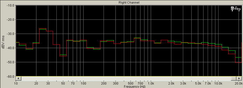
As a matter of fact, I give more importance to the in-room response, since it better depicts what arrives to our ear; so I positioned both speakers in their final room position and the mic in place of my ears; both speakers were playing, receiving a 1/3 octave pink noise signal from two generators, thus each speaker was playing a different signal: in case you don’t have two signal generators, you can create a wave file with the program Sound Forge (that is capable to generate a not cyclic track, different for each channel), and then burn a CD with it to use your CD player as a double pink noise generator: if you are interested, in the Home Page download folder there is a ready to use downloadable wave file. I also find important to have a reference response for comparison, since it helps understand what is due to the speaker and what to the room acoustic: I used a pair of Dynaudio Contour 1.8 MKII for the purpose. Another big reference help comes from the Henning Møller curve4, which shows the optimum curve for Hi-Fi equipment measured in listening room: even if Møller study have been presented in 1974, I think it has been forgotten by the most! I have been lucky to know Renato Giussani, the Aedon Audio NPS-1000 designer, that being a journalist of an Italian Hi-FI magazine at that time, personally assisted to Møller workshop and keeps transmitting this precious information to people, like me, that were too young for AES papers reading. Finally here's the in-room 1/3 octave pink noise response, measured on axis and 30° off-axis with the above said method.
 |
|
Auri: in room response on axis and 30° off axis, both speakers playing |
Conclusion
I am satisfied with music coming out from Auri, especially for the bass region where the double chamber reflex works very well; I liked the ribbon tweeter, as rich of details, but I will probably go back to use a classic dome for my next project, cause I am more used to their sound. The best in room position of the speakers was found placing them at least 50 cm from the back wall and oriented parallel to each other; unfortunately Focal is not selling home components anymore, so it’s up to you to search in the dealer’s stock or to find a valid substitute for the 7K4412.
Reference:
Joseph D’appolito "Testing loudspeakers", 1998, page 59; James Moriyasu "Acoustic diffraction: does it matter?", Audioxpress 2/2003.
Vance Dickason "The loudspeaker design cookbook", 2000, fourth edition, page 102.
James Moriyasu "Panel damping studies", Audioxpress 2/2002.
Henning Møller, "Hi-Fi Tests-with 1/3 Octave Pink Weighted Random Noise", AES convention 47 (February 1974), preprint Number A-5.