|
|
|
by Jose Sasian e-mail: jose.sasian@optics.arizona.edu
May 2004
Background
Last August I was bitten by the bug of speaker building and HiFi sound. What an amazing hobby! It combines several disciplines such as electronics, acoustics, music, woodworking and art. All make such terrific synergy. The upcoming of programs like Speaker Workshop allow almost anyone to do a host of interesting acoustical experiments and fine tune speaker systems. Indeed, judging by the excellent web sites, the speaker building hobby is just booming.
I wanted to learn about HiFi and speakers and was surprised by the wealth of ideas, systems, and innovations. Then I set the goal of building a system that could make me think I had an orchestra or musical group in front of me in a small room that now is my music room. I did not know then if this was possible. My speaker building skills have been gained from web sites. I particularly enjoyed Arthur Ludwig, Lynn Olson, and James Melhuish’s web site. Claudio Negro kindly helped me with Speaker Workshop questions and I thank him for hosting this project.
Speaker Workshop
Speaker workshop from AUDUA is a wonderful tool! I spent too much time learning it and suggest learning it from someone who knows it rather than trying it on your own. It is definitely worth and necessary to learn Speaker Workshop. Many thanks to the developers for making it available free of charge.
System concept
Since stereo imaging was of prime importance I realized that I had to explore speaker dipoles because they have the advantages of not radiating unnecessary sound that can veil and confuse the sound stage.
For reference, Dan Russell http://www.gmi.edu/~drussell/Demos/rad2/mdq.html has posted some insightful animations of dipole and other speakers. Neil Muncy has pointed out in “Stereo Imaging” http://www.professional-sound.com/sound/sum923.htm that placing one speaker in front of the other and noting how the sound significantly decreases when the speakers are connected out of phase is a test for the symmetry of the speakers. Symmetry of speaker construction and placement are critical factors. The article “Loudspeaker Imaging Theorem” by Jeff Bagby http://diyaudiocorner.tripod.com/imaging.htm also points at several factors influencing speaker imaging.
Speaker dipoles emit a more organized in-space sound field than omni directional speakers which create a confused sound field. The difference can be heard if attention is paid, especially in the low frequency end. The advantages of a speaker dipole are:
1) Dipole radiation with less unnecessary energy emitted.
2) Dipoles can operate at Fs which is a gain with respect to closed or vented systems.
3) No baffle and therefore minimum cabinet resonances or stray sound
4) Smaller in size than the equivalent boxed speaker
5) A sense of an organized sound field
6) Ease of fabrication
7) Low cost!
|
|
|
|
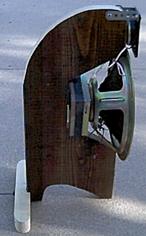
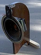
Figure 1. Prototype speaker dipole: woofer and tweeter
|
I arranged a woofer and a tweeter as shown in Figure 1 to form the left and the right channels. Speakers, woofer and tweeter, are completely open with no back cover so that they work as dipoles. I wanted to use a dome tweeter but discovered with Speaker Workshop that dome tweeters have a much more omni directional sound field which produces unwanted sound reflections as compared to an open-cone speaker tweeter. With a dome tweeter I was seeing a floor reflection in the pulse response which disappeared when I switched to a dipole tweeter. My ten inch woofers came from an Infinity QA speaker pair and the tweeters were intended for car audio and have a Ford marking. I used two Kenwood KM206 amplifiers at 150 watts rms per channel, one for the woofers and one for the tweeters. There are no crossovers at all. Instead two ten-band BSR 3000 graphic equalizers are used to send the low frequencies (about 2500 hertz or less) to the woofers and the highs (2500 hertz or more) to the tweeters. The equalizers also are used to flatten the dipole frequency response. So this is a biamped system with equalizers instead of crossovers. The extra amplifier power insures that there is little or no distortion due to amplitude clipping.
One disadvantage of a dipole is the lower efficiency. This drawback was minimized by using the Kenwood KM 206, 150 Watt per channel amplifier and having no crossover network. Another disadvantage is that a dipole needs drivers capable of large displacements.
The room
At the beginning I was not sure what room in the house was best to set the system. There were two options, the living room and a small room. I decided first to understand the acoustics of the smaller room which measures 2.74 m/3.35 m/3.66 m (H,W,L). The first longitudinal modes for this room are 47Hz, 51Hz, 63Hz. Dan Russell has also posted some nice 1D animations of the effects of speaker placement in a room and made a number of interesting observations.
|
|
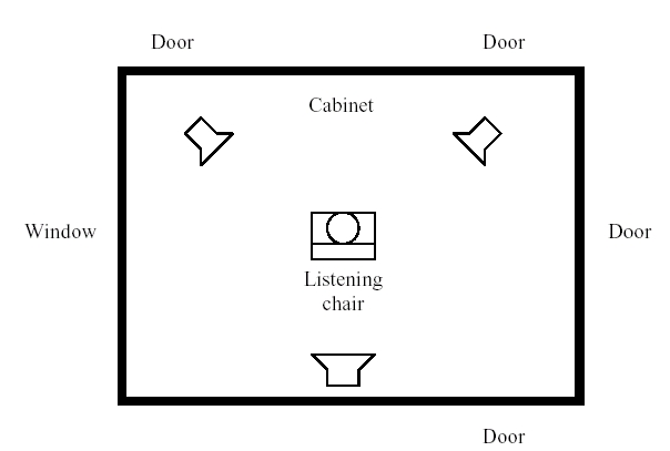
The room arrangement is shown schematically in Figure 2. It has four doors and one large window. The speaker dipoles are set at approximately 96 degrees with respect to the listening chair and about 1.37 meters from each ear so the speaker separation is about 2 meters. I tried several chair/speaker arrangements such as placing the chair near a wall and the speakers toward the center or placing the speakers along the width of the room. The best placement I found is shown in Figure 2. The woofers are placed at the ear level when I am sitting and positioned 0.5 m from the front wall and 0.6 m from the side wall. For stereo imaging purposes fine tuning of the system required to locate the speakers to within one inch and to about two degrees. The speakers are not directed toward the ear of the listener as shown in Figure 2 but point towards the opposite wall where a third speaker for ambience effects is located.
The use of dipole speakers makes room treatments not as important as with omni-directional speakers. Significant sound reflections are believed to veil the imaging or reduce the sound transparency.
Equalizing the speakers
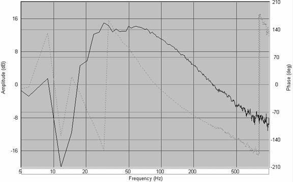
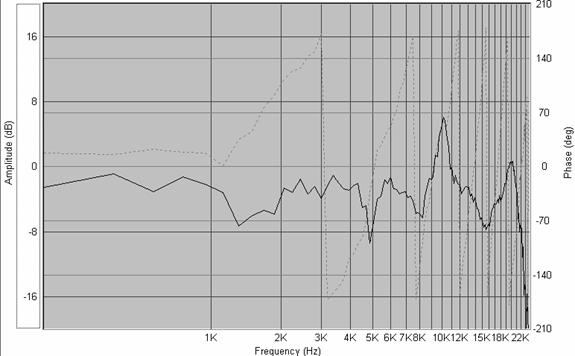
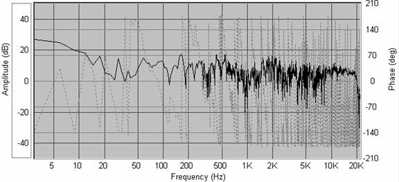
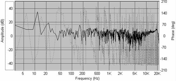
I used Speaker Workshop and the BSR graphic equalizers to flatten the frequency response of the speakers as shown in Figures 3 and 4. The equalizers are connected before the amplifier and no crossover of any type is used. Though at times I wonder if a Zobel network should be included to flatten the impedance curve and ease the job of the amplifiers. There is one amplifier and one equalizer for the woofers and another amplifier and equalizer for the tweeters. Figure 3 is the on-axis response of the dipole and Figure 4 shows the near field response. The equalizer’s frequency levers were adjusted by trial and error to achieve a flat frequency curve. The strong slope of the near field curve actually flattens at the listening distance of 1.37 meters from each speaker. The response of the speaker goes down to 30 Hz and to about 18 KHz. I can hear at 47 years old up to 15.5 KHz with my left ear and to 15.0 KHz with my right ear.
|
|
|
Figure 3. On axis frequency response at 1.37 meters |
The dB variations (power dB) of the frequency curves are in the order of +/- 7 dB at around 10KHz and below 8Kz the variation is smaller. This is not superb but I think I can hardly hear such variations.
|
|
|
Figure 4. Near field frequency response |
Figure 5 shows the ungated frequency response of the dipole speaker including the room response at the listening chair. Note that the bass response flattens at the listening position of 1.37 meters. In addition the comb filtering effects around 50 and 100 Hz are apparent. This probably has to do with the central position of the listening chair since the first axial mode’s (47Hz, 51Hz, 63Hz.) nodes are located in the room’s center as are the second axial mode’s (94 Hz, 102 Hz, 126 Hz) antinodes. Figure 6 is a 1/3 octave smoothing of the in-room response.
|
|
|
Figure 5. Ungated dipole speaker and room response
|
|
|
|
|
|
Figure 6. 1/3 octave smoothing of graph in Fig. 5 |
Testing and adjusting for imaging resolution
Using Speaker Workshop I set several signals with pink noise in the frequency ranges of 32-64Hz, 64-128Hz, 128-256Hz, 256-500Hz, 500-1Khz, 1-2KHz, 2-4Khz, 4-8KHz, and 8-16KHz. Then I listened at each range and noted the width and position of the phantom sound image. Extending my arms and setting limits with my hands to the extent of the pink noise phantom image I was able to determine its angular width which was about 4 degrees at high frequencies and 12 degrees at the lower frequency range. I had to make some adjustments to have the phantom image centered in front of me for all of the above frequency ranges. The room has an acoustical asymmetry given the large window and doors and this asymmetry increases if the door opposite to the speakers is left open.
I used the balance control of the preamplifier to shift from left to right and from right to left the phantom image at each frequency range to check for the number of resolution steps over the 96 degrees angle between the speakers and the listening chair. I could perceive around 18 distinct positions for the phantom image at high frequencies and less at lower frequencies. Setting the pink noise from 64 Hz to 16 KHz produced a phantom image of about 12 degrees. There are more resolution cells at high frequencies than at low frequencies and this confirms the better imaging of high pitched sound sources. Since the angular resolution of the ear is in the order of 3 degrees (when the source is in front and at reasonable frequencies) I know that my speakers are near or at top performance in this respect.
It appears to me that sound reflections that arrive more than 1-2 milliseconds later than the primary sound do not reduce the imaging but can reduce the transparency of the imaging stage. The sound reflections can enhance the perceived ambience but if there is too much stray sound energy then the sound stage transparency suffers. Imaging is more a matter of symmetry of the speakers, room acoustical symmetry, audio equipment symmetry, and what happens in the first millisecond. Using a Boss RPD delay in one channel I could introduce a simulated sound reflection which actually was contributing to the sound ambience without reducing the imaging.
The omni directional sound of a standard speaker and its stray sound tend to veil the transparency of the sound stage. In my music room the sound of a dipole speaker appears to be more organized and clearer than the sound from an omni directional speaker.
Dusty balance knobs or switches in the Kenwood Basic 2 preamplifier I used gave me electronic asymmetry problems. I read that bad caps also influence the imaging which is understandable if they introduce phase or amplitude asymmetries.
Chromatic scale test
I used an electronic keyboard to test the lower frequencies. This was actually a severe test for the woofer and its stand since it clearly showed resonances as I played through all the keyboard notes.
The rear speaker
The rear speaker is a must-have addition and has two purposes. The first is to produce some ambience and to contribute to produce the effect of being in a large room since the sound is delayed electronically by about 24 milliseconds. The second purpose is to contribute to make the front speakers disappear. If only one speaker is playing the ear can distinguish that the sound is coming from a localized source. With the delayed sound of the rear speaker the sound from the front speaker losses its localization. The sound level of the rear speaker is not loud enough to conflict with the imaging of the front speakers. I am feeding one channel, the L or the R, to the rear speaker and probably should feed the L+R signal. The L-R signal produces some horrible noise when high frequencies are being played. The third speaker enhances the 3-D sound effect. In summary, the rear speaker significantly contributes to create a realistic sound field.
The performance
The music I hear is three-dimensional and by far exceeds my original expectations. At each system improvement I would call my wife Wasi to ask for some kind of reassurance that the system was improving. She has a very finely developed ear that can hear fine details. I fined tuned the system and played a piano piece “Melodia del Rio” by Ruben Gonzales which brought tears to my eyes from the emotion of hearing a great music piece with amazing sound quality. I did not have to ask anyone about the quality of the system, I knew, I had the certainty, that I had built something really amazing.
It is amazing because of the precise imaging and transparency.
The sound stage is wide and deep and depending on the recording instruments it can be positioned in a horizontal field of +/- 50 degrees covering at times more than the angular span of the speakers. The fact that the tweeter is slightly above the woofer contributes, I think, to having a vertical span from about 1/3 the height of the room to the ceiling or beyond. The instruments can be located from about 1 meter to a large distance. The imaging is precise. The room is converted into a concert hall, into a church, or into other musical spaces.
I recommend the Glenn Miller orchestra Swing Time CD 7055-2, Ranwood records. This CD has wonderful music with wide and deep sound stages, bass to hear, transients, and vocals. Other Glenn Miller’s recordings that I have heard are horrible. The Ranwood records, Glenn Miller’s CD provides an awesome glimpse into what could have been the original Glenn Miller’s sound.
Further improvements
There are areas of improvement. The drivers need to be replaced by high quality ones so to further flatten the highs and extend their range. The lower bass has some resonances and the cone reaches at times the maximum displacement. The driver stands also have resonances that need to be dampened. Despite of these problems none of the other speakers I have, KLH model five, Klipsch KG 2.5 , Infinity, DCM DX-12 produce the clarity and imaging that these speaker dipoles are capable of.
In a technical note it would be helpful to device tests for transparency and transients.
Conclusions
One can easily assemble speaker dipoles that are capable of amazing sound. Speaker workshop is a wonderful tool that permits fine tune speakers and make acoustical experiments. The test described here, to check for the phantom image symmetry across the frequency range, might be a useful contribution to the hobby of speaker building. This project can be recommended as a first speaker project.
Addendum A
Claudio suggested including Speaker Workshop graphs with expanded scales so here they are for the near and on-axis responses.
|
|
|
Fig 7. Near field response with expanded vertical scale |
|
|
|
|
|
Fig 8. On-axis response with expanded vertical scale |
Addendum B
In Figure 9 are shown the first three room axial modes along the width of the room in relation with the dipoles and the listening chair. The dipoles are in the nodes of the third mode and the chair is in the node of the first mode. This placement inhibits those modes and this is shown in the in-room response of Figures 5. Moving the chair position about 0.35 meter closer to the speakers improves the low frequency, 20-50 Hz, response. As suggested by Figure 9 the bass response also improves when both the speakers and the listening position are closer to the wall.
|
|
|
Figure 9 |
The width of the room, the first 51 Hz, second 102 Hz, and third 153 Hz modes, the position of the dipole and listening chair. Note that because the dipole or the listener is located at nodes of the first and third modes the response is decreased. This is in agreement with the in-room, ungated response of Figure 5.
In playing Mendelssohn’s Wedding March (Organ Spectacular, Peter Hurford, CD London 430710-2) and alternating the listening position from the center of the room to about 0.5 m closer to the speakers, the bass perception changes. At the room center the sound appears more organized and the bass field is less obvious. Off the room center and closer to the speakers there is a rich presence of the bass field though some confusion in the sound field seems to appear. For this comparison I had the speakers 0.25 m from the wall so that the bass could be better coupled to the room.
The center of the room is an interesting listening position because many modes have their nodes there. This listening position may contribute to the transparency of the sound at the expense of a volume decrease of some frequencies in the bass response.
Interesting discussions about room modes and speaker placement are given at:
http://www.asc-hifi.com/articles/ht1.htm,
http://www.harman.com/wp/pdf/MaximizingLoudspeaker.pdf,
http://www.gcaudio.com/resources/howtos/roomacoustics.html .
Addendum C
Here are given the responses of a second generation pair of dipoles using KLH model five woofers and Sansui dome tweeters as shown in Figure 10.
|
|
|
|
Fig 10. KLH model five woofer and Sansui dome tweeter dipole prototype |
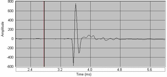
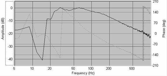
Figure 11 shows the pulse response which is about 0.3 ms in width. Figure 12 shows the near field response.
|
|
|
Fig 11. KLH model five woofer and Sansui dome tweeter pulse response |
|
|
|
|
|
Fig 12. KLH model five woofer and Sansui dome tweeter near field response |
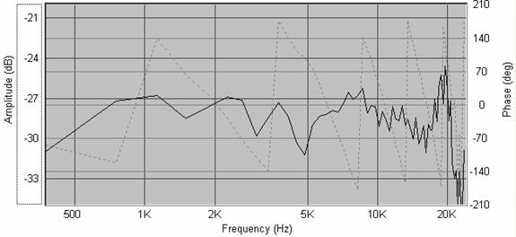
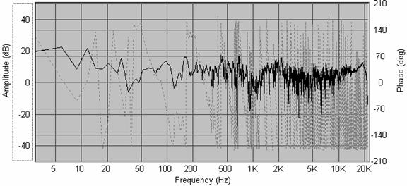
Figure 13 shows the on-axis response. Figure 14 shows the in-room, ungated response at the room center.
|
|
|
Fig 13. KLH model five woofer and Sansui dome tweeter on-axis response |
|
|
|
|
|
Fig 14. KLH model five woofer and Sansui dome tweeter ungated in-room response at room center |
Figure 15 shows the in-room, ungated response sitting about 0.35 m closer to the speakers. Note how the bass responses at about 20-50 Hz. improves as the listener is slightly away from the room center. Figure 16 shows the in-room, ungated response when the speakers are closer to the wall (0.25 m from the wall as compared to 0.5 m in the other measurements) and the listening position is about 0.5 m off-the room center and closer to the speakers. Note again the improvement in bass response by raising the lower bass and removing the dip of the third axial mode.
|
|
|
Fig 15. KLH model five woofer and Sansui dome tweeter ungated in-room response 0.35 m off the room center |
|
|
|
|
|
Fig 16. KLH model five woofer and Sansui dome tweeter 0.25 m away from to the wall and listening position 0.5 m closer to the speakers |
With these dipoles I can notice more presence of the high frequency range and less spurious sound in the very lower bass due to occasionally reaching the maximum allowable cone displacement. Spurious sound can be caused by the surround hitting the basket, the spider self-rubbing, or the coil hitting the magnet plate when playing very low frequency music like organ music. In addition, I can perhaps notice a decrease in the sound stage transparency given the omni-directional dome tweeters. These second generation dipoles provide a very flat response and also sound great. Next a subwoofer companion!