|
|
|
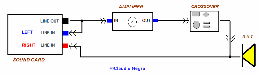
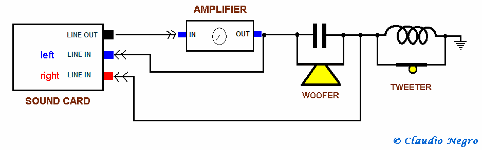
Cables using LINE OUT as reference |
It is possible to measure, through Speaker Workshop, the series and parallel Network Transfer Function (NTF) using the real load, that is the driver. With this measurement, we can predict the drivers response with the filter, without needing to measure its frequency response with the filter. The procedure was first introduced, as far as I know, by Guglielmo Caioli in June 2002 in the Audua Forum, but without much interest of the community. Then the efforts of Valerio Russo and me, helped to diffuse the Caioli's method, that have been included in the second version of Jay Butterman's “The unofficial Speaker Workshop manual”.
Let's start with defining the network transfer function: it is the linear mapping of the Laplace transform of the input to the output of the filter; that is the same as if we apply a signal (of known amplitude and frequency) Vin at the input of the filter and we measure its amplitude at the filter output, Vout. Then the relation Vout/Vin is the network transfer function at that frequency; changing the frequency of the signal is possible to calculate all the point of the NTF for the desired frequency range: it's a long and tedious job, but it can be performed quickly using Speaker Workshop and the Caioli's method!
The cables
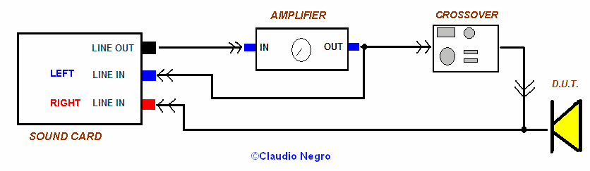
Here is the necessary connections: basically it's like doing a frequency response measurement, but the amplifier output is connected to the filter input and the filter output is connected to the driver and to the DATA channel of the sound card (LINE IN right); for the Reference channel (LINE IN left) we can use the sound card Line Out or the amplifier Output: don't use more than 500 mV from the amplifier Output, otherwise you can burn the sound card. Using the amplifier Out as Reference, gives some advantages: since SW measures the voltage difference between the Data and Reference channel, the amplifier gain will not be taken into account, therefore the chart will show 0 dB of filter attenuation in all the range where the filter is not working! Moreover if we sum the NTF chart to the driver unfiltered response chart, we obtain the filtered driver response.
With the Caioli's method we measure the Network Transfer Function with the real driver impedance: thus we can verify if our filter is right as we wanted, since it is very common that, in complex filters, the components tolerance brings to different than needed filters.
|
|
|
Cables using LINE OUT as reference |
|
|
|
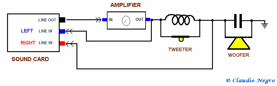
Cables using Amplifier OUT as reference |
|
|
|
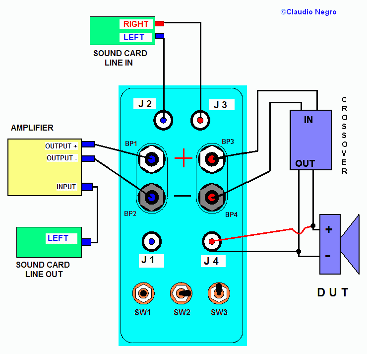
Cables using the Wallin Jig II |
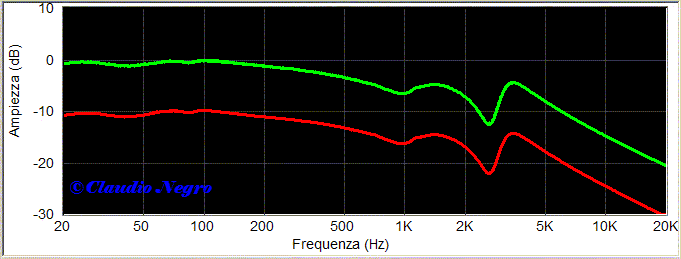
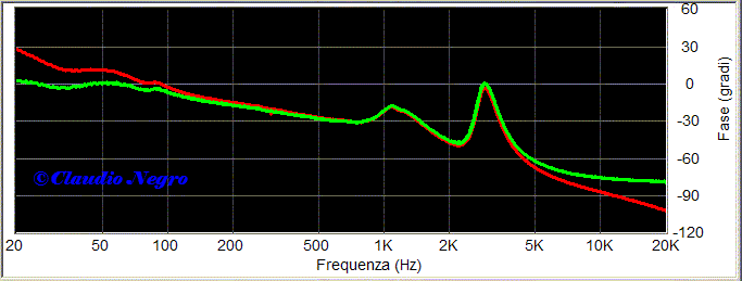
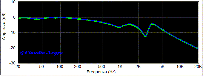
Once the cables are ready, assuming you have already performed the sound card calibration procedure, put the amplifier volume to its minimum, and connect a voltmeter to its output; then create a new signal, RESOURCE/NEW/SIGNAL, or use one you already have; double click on it and then MEASURE/ FREQUENCY RESPONSE and increase the ampli volume till you read a 300-500 mV AC on the voltmeter. Repeat the measurement till you get the desired volt reading, and pay attention not to fry the sound card, especially if you are using the amplifier output as Reference: as a precaution, you can disconect the LINE IN mini-jack, remembering to connect it once the volume have been set. When the volume level is OK, repeat the measurement and open the newly created file, that is the Network Transfer Function: in the next chart I compared the NTF of the same filter measured using, as reference, the Amplifier Output and the Line Out; as you can see, the only difference is in the amplitude level. The filter is a second order pass bass, with 2 parallel RLC in series with the Focal woofer.
|
|
|
N F T : freq. response with Ampli as reference and with Line Out as reference |
Now let's take a look at the phases: here the limit of the measurement made with the LINE OUT as reference comes out; in fact at the band extremes, the phase is wrong.
|
|
|
N F T : phase response with Ampli as reference and with Line Out as reference |
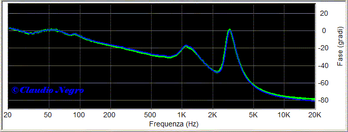
To check how reliable the measurement is, I compared it with the NTF calculated by a simulation software using the driver impedance and the same filter used. The result below speaks for itself:
|
|
|
N F T : frequency response with Ampli as reference and simulated |
|
|
|
|
|
N F T : phase response with Ampli as reference and simulated |
If we have used the Ampli Output as
reference, we can sum the NTF and the unfiltered driver
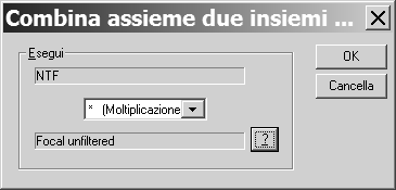
response to get the filtered driver response: open the NTF chart (the one measured using the amplifier as
reference) and click on CALCULATE/ COMBINE; a window will appear and choose
MULTIPLY and then click on
![]() to select the unfiltered measured driver response file:
to select the unfiltered measured driver response file:
|
|
After clicking on  we will see, in green, the driver frequency
response chart, obtained through the sum of the network transfer function and
the unfiltered response of the Focal (it is the gated far field measurement,
therefore it's not useful below 300Hz); to verify the method I added,
in violet, the measured frequency response of the filtered
Focal (gated far field):
we will see, in green, the driver frequency
response chart, obtained through the sum of the network transfer function and
the unfiltered response of the Focal (it is the gated far field measurement,
therefore it's not useful below 300Hz); to verify the method I added,
in violet, the measured frequency response of the filtered
Focal (gated far field):
|
|
|
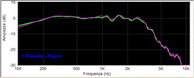
Filtered Focal Freq. Response : Calculated - Measured |
I repeated the procedure for the ATD tweeter, that uses a third order filter, and once again the comparison chart shows the reliability of this method:
|
|
|
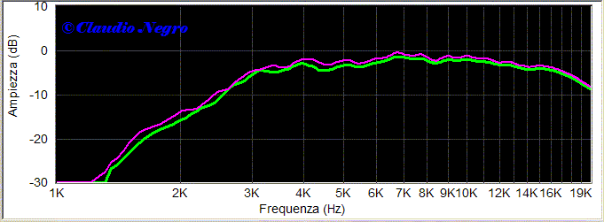
Filtered ATD Freq. Response : Calculated - Measured |
Measuring a series filter
It is possible to use Speaker Workshop and the Caioli's method also to measure the NTF of a series filter, using the symmetry of this kind of filter. The measuremet procedure is just like the one used in the parallel filter: what changes is the connection and the need to use the amplifier output as reference. As you can see below, is sufficient to change the position of the woofer-capacitor block with the tweeter-inductor one; remember that both the drivers need to be connected, otherwise the NTF will be wrong.
|
|
|
Series filter connections |
|
|
|
Series filter connections |
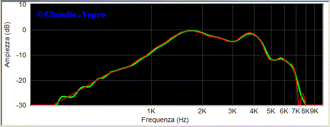
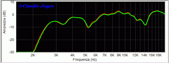
Even with the series NTF we can preview the driver filtered response, summing the driver series NTF to the unfilterd driver response, using the same procedure seen in the parallel filter therefore I will not repeat myself. To check the results, I compared the calculated driver under filter response with the one generated by a simulation software: in this case I couldn't compare with the measured response since, in a series filter, you cannot disconnect one driver because it will change the load seen by the filter and, therefore, its network transfer function. The drivers measured are car components filtered with a 1.4 mH inductor and a 16 micro Farad capacitor.
|
|
|
Filtered woofer Freq. Response : Calculated - Measured |
|
|
|
Filtered tweeter Freq. Response : Calculated - Measured |
In conclusion, we have a measurement method that allows us to verify the network we are going to use, comparing it with the simulated network and showing us the driver filtered response before we have actually measured it. Not bad, right?