|
|
|
Phase variations on 3 measurements: woofer |
A critic part of Speaker Workshop is the Phase, since it's possible to have latency changes, therefore the starting point of the impulse response can vary: to see it, just repeat many times a impulse response and check if the the first impulse always starts at the same time point. If the start of the impulse is different during two measurements, the phase too will be different. With the Terratec DMX the variations happen inside 0.01 ms (remember that 0.1 ms corresponds to 3 cm). This is a limitation of SW and of the sound card, therefore is better to use WDM drivers that gives some stability. Knowing this, it will be impossible to know exactly the real phase, nor the time of flight, nor the real offset between the drivers. Moreover, the obtained relative phase of different drivers are not comparable for crossover design, depending on how much the impulse start jumps. To show you the problem, I made an acoustic measurement that I used as reference; then I repeated the measurement 3 times, without changing anything. I compared each measurement to the reference one, and I made a chart in which the phase differences were shown:
|
|
|
Phase variations on 3 measurements: woofer |
All the measurements are gated far field, with 10 repetitions: the Focal woofer has a phase change lower than 1° till 3000 Hz, therefore it's not a big problem. I repeated the comparison with the ATD tweeter, and the results are positive too:
|
|
|
Phase variations on 3 measurements: tweeter |
|---|
Speaker Freq. response with filters:
measured
-
simulated
An even more precise method of measurement is to: 1)
Measure the first driver and check its reference impulse response (file
Measurement.in.l that is located in the SYSTEM folder) to know at how
many ms the first impulse starts: write it down. 2)
Measure the second driver and again check its reference impulse response
looking at the file Measurement.in.l located in the SYSTEM folder to know
at how many ms the first impulse starts: it has to start at the same ms of the
first driver. If it doesn't, repeat the second driver measurement till the two
values are equal.
The above method is valid only if the input channels (left and right) of
your sound card have equal or constant latency: to know it, connect the Line
In and Line Out of the sound card with a Loop Cable (left
Line Out connected to both left and right Line In); create a new
SIGNAL by clicking on RESOURCE / NEW / SIGNAL or use one that you already have;
double click on the SIGNAL then MEASURE / FREQUENCY RESPONSE. Always verify in
the SW Vu-Meter that you are not clipping the signal; now double click on
Measurement.in.l located in the SYSTEM folder and a chart will open; right
mouse click inside the chart and ADD the Measurement.in.r located in the
SYSTEM folder too. Zoom in the area were the impulses start: if the two impulses
start at the same time, you are a lucky man! Probably the two impulses do not
begin at the same time, therefore calculate of how many ms is the difference
between the two impulses start and write down the value; now repeat this
measurement many times (double click on the SIGNAL then MEASURE / FREQUENCY
RESPONSE), and each time write down the impulses start difference: if this
difference value is constant, thus the two channels move together even if
shifted, you can use the described method.
So till now we have seen that if the latency problem, that makes the
first impulse not to remain stable at one position (it
sort of jumps around on the horizontal time axis), is small, 0.01 ms in my case,
there will be no problem in the crossover simulation. Further more, we have seen
a method that allows an even more precise phase measurement, at the cost of an
extra measurement time. But what happens if our sound card is too jumpy in
latency? For cases where the first impulse moves very much, I (with Bruno
Dalle
Carbonare and Valerio Russo) have studied a procedure to calculate
the minimum phase for each driver: doing this, we can overcame a changing
impulse start problem since the minimum phase is calculated through the driver
frequency response and Hilbert transform. First thing to do, is to export
the response from SW, then convert it into logarithmic scale by using a program
that is found in the
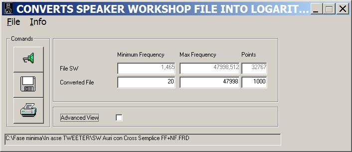
Let's start opening the conversion
program, and loading the file exported from SW by clicking on
![]() :
:
|
|
In the fields Frequency you will read the imported file limits, while
below them you can write the minimum and max frequency desired, and the number
of resolution points. It is wise to choose the frequencies where the measurement
is clean, thus without noise. In my example I have chosen 235-47999 frequency
band and a resolution of 1000 points. Then click on
![]() and the logarithmic
converted file is saved in the same directory where the original file was.
Marking on ADVANCED VIEW, some more program options are activated: I leave to
you the pleasure to discover them! Of course you can use this program also to
convert impedance measurements.
and the logarithmic
converted file is saved in the same directory where the original file was.
Marking on ADVANCED VIEW, some more program options are activated: I leave to
you the pleasure to discover them! Of course you can use this program also to
convert impedance measurements.
Now let's open the Excel file Frequency response combiner: check in the
Links to download it:
|
|
1) Load the logarithmic converted file by clicking on EXECUTE. In this column you will read also the file frequency limits and number of points, that has to be equal to the ones chosen during the conversion.
2) Select 1Drv Base e Precise Phase & Group Delay then click on Extract Minimum Phase and after some seconds the minimum phase will be calculated through Hilbert transform. To save the new file, go back to circle 1 and click on LOAD so that it changes to SAVE and then EXECUTE: you will be asked where to save the new file.
It's important to know that this method works well if the drivers response is well extended in frequency: David L. Ralph illustrates the problem in his “Hilbert Transform Generated Minimum Phase & Errors” and “Driver Model Accuracy and its Impact on Phase". So it is important to use the complete response for the woofer (near field + far field) and to get a well over 22k Hz response for the tweeter: if your sound card reaches 96k Hz of S/R, the problem is solved since it will allow you to get a measurement till 48k Hz. If your response reaches only 24k Hz (sound card with a S/R of 48k Hz), you can use the NORMALIZER, to extend the response both in the low and high region, with the desired slope. Remember to calculate the minimum phase after having used the NORMALIZER as showed in the circle 2. It's useful to use a calibrated mic with a linear extension well beyond the 20k Hz.
To test the procedure I repeated the comparison made in the beginning, that is I imported in a crossover simulation program the minimum phase responses calculated by FR Combiner, and I changed, in the simulation program, the woofer offset till the measured total response (all the drivers working) and the simulated total response were coincident. Then I connected a II° order filter on both the drivers, crossed at 3000 Hz, and compared the speaker simulated response with the speaker measured response and the result is, IMO, positive:
|
|
|
Minimum phase freq. resp. with filters: measured - simulated |
|---|
Now that I showed you the way to go, experiment yourself and have fun!