|
|
|
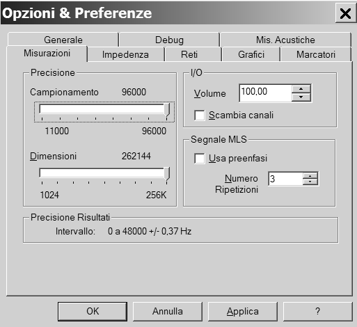
Using RMAA we understood which sample rate and volume we have to use in Speaker Workshop. First we call the chosen volume set through QuickMix, then we open SW and go to OPTIONS/ PREFERENCE/ MEASUREMENT and select the chosen SAMPLE RATE and slide to the maximum the SAMPLE SIZE; to improve the measurement increase to 3 the REPEAT COUNT. Now click on the IMPEDANCE tab:
|
|
|
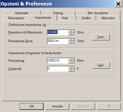
First we test the Sound card impedance: connect the Impedance Cable to the SC substituting the green cable, till now used (LOOP CABLE), with a 10k Ω resistor:
|
|
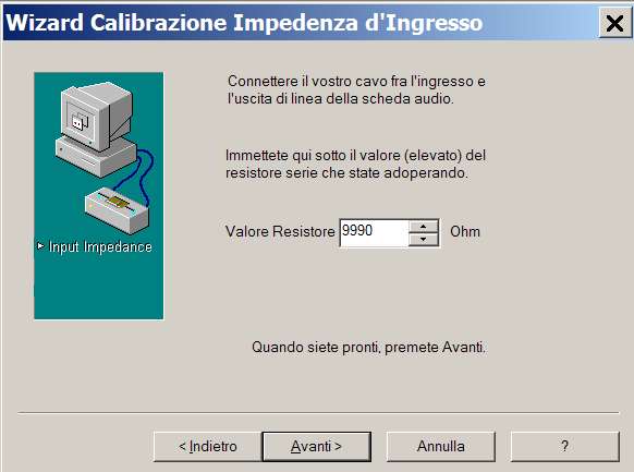
Before connecting the resistor
measure it with the multimeter, and write down its value; then click
on
![]() and in the new window that will appear will be explained how to
connect the resistor to the SC (as we already did); click on NEXT and
write the value of the resistor as measured with the multimeter (in
my case 9990 Ω).
and in the new window that will appear will be explained how to
connect the resistor to the SC (as we already did); click on NEXT and
write the value of the resistor as measured with the multimeter (in
my case 9990 Ω).
|
|
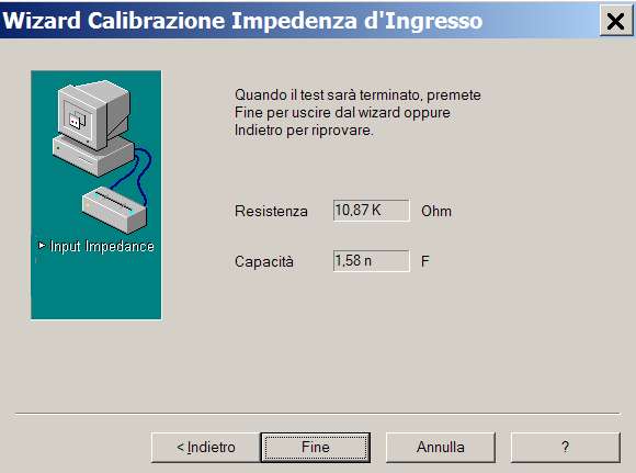
Click on NEXT and after few seconds we will see :
|
|
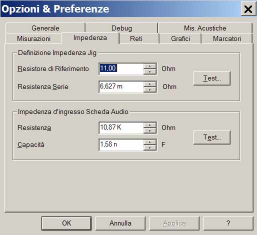
So our sound card has an impedance of 10,870 Ω and a capacitance of 1.58 nano Farad. Click on END. However, some users reported wrong sound card impedance measurement, so you can just write zero for the card capacitance and get the impedance from the sound card technical specification (normal values are 47k for consumer cards and 10k for pro ones). If you are using an amplifier with voltage divider, you must add its value to the SC impedance, by the formula: Ztot=R1 + R2*Zin / (R2+Zin). So if you are using the voltage divider I showed before (1k and 200 Ω) and assuming a SC impedance of 10k we will have: Ztot = 1,000 + 200*10,000 / (200+10,000) = 1,196 ohm, that is the value to write in the SOUND CARD INPUT Resistance.
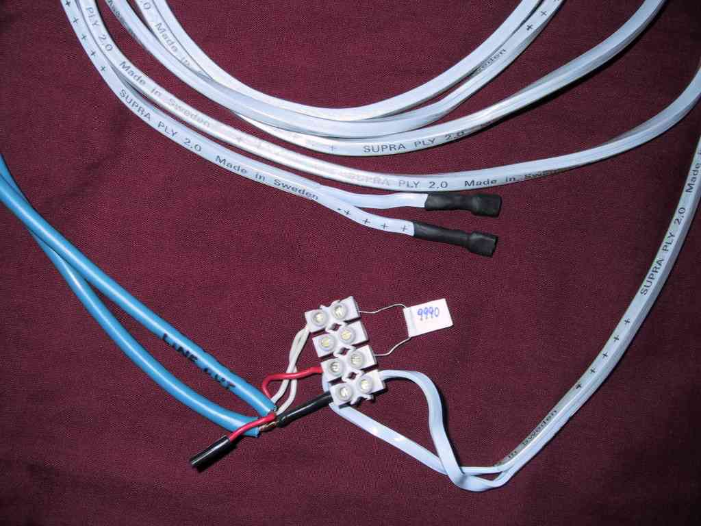
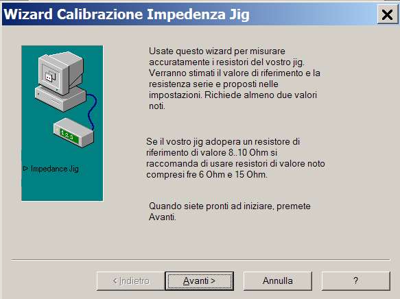
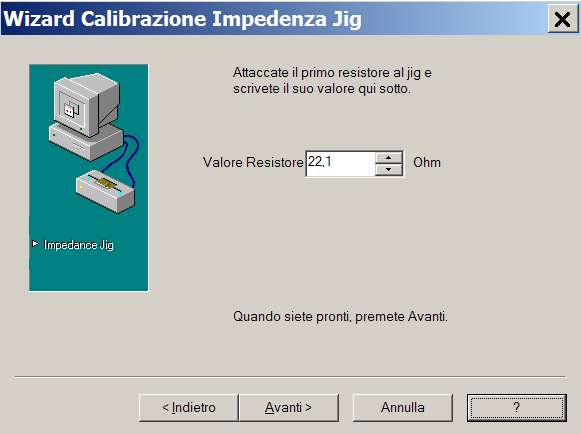
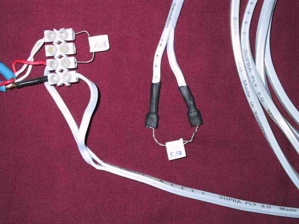
Now it's time for the Impedance JIG definition, for which we need 3 resistors: (between parenthesis the values I used)
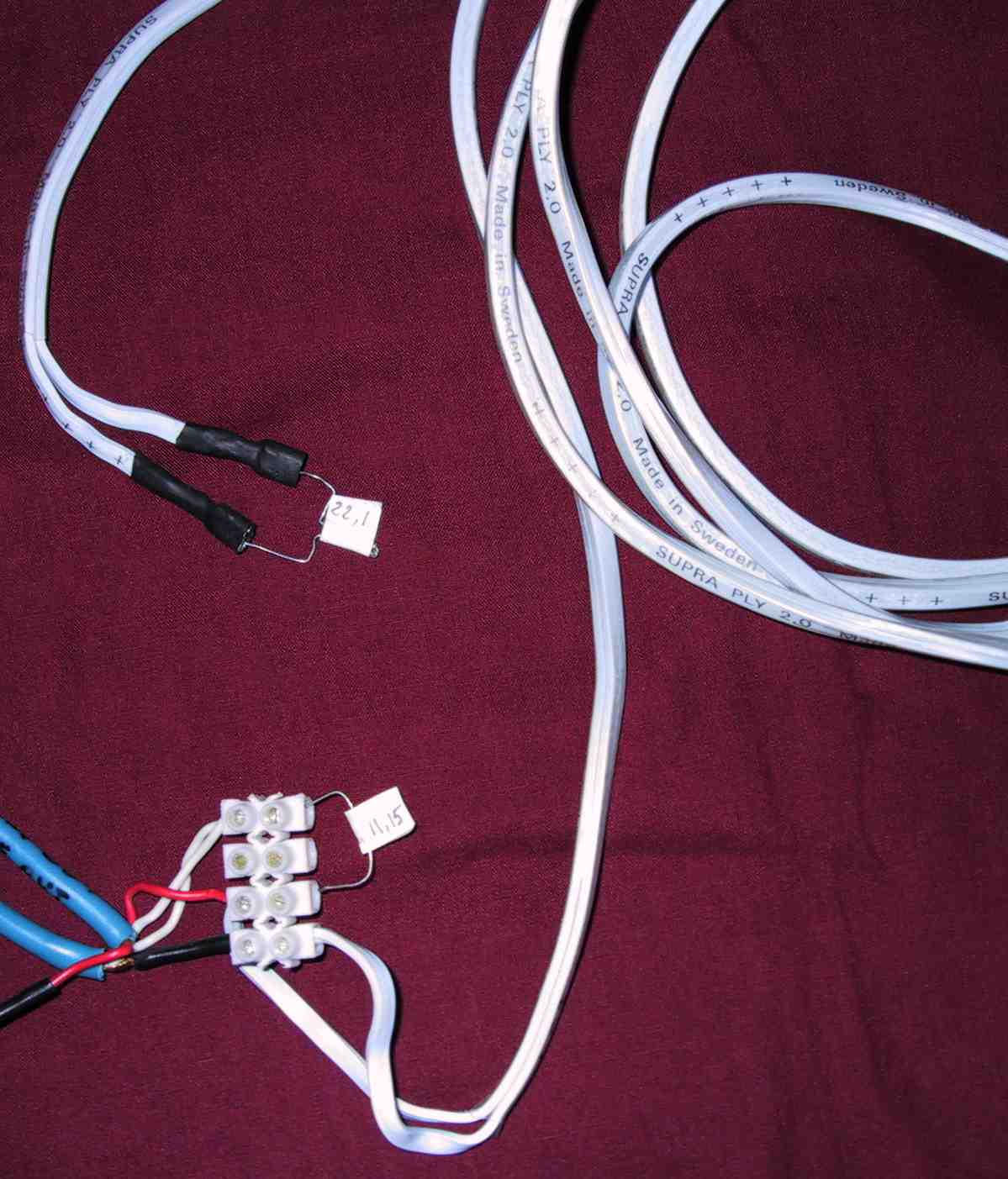
1) REFERENCE RESISTOR (11.15 Ω) that has to be connected to the IMPEDANCE CABLE in place of the 10k Ω resistor we used in the Sound card impedance test.
2) CALIBRATION RESISTOR (22.1 Ω) whose value has to be around twice the reference resistor one and it will be connected to the DUT CABLE connectors.
3) CALIBRATION RESISTOR (5.58 Ω) whose value has to be around half the reference resistor one and it will be connected to the DUT CABLE connectors.
We measure through the tester the 3 resistors writing down their values. If you use a low resistance value meter, measure the Series Resistance of the cable (measuring it by connecting one terminal of the DUT CABLE with the RIGHT LINE IN MINIJACK); moreover measure the multimeter cables resistance and subtract its value from the resistors measured values.
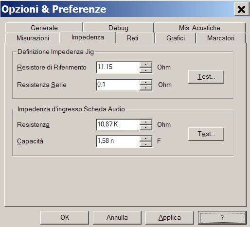
Back to SW, write the Reference Resistor and Series Resistance (if you didn't measure the series resistor just leave it to the default value of 0.2 Ω). Click on APPLY:
|
|
Then on
![]() :
:
|
|
Click on NEXT and with the REFERENCE RESISTOR (11.15 Ω) connected to the IMPEDANCE CABLE and the first CALIBRATION RESISTOR (22.1 Ω) connected to the DUT CABLE, write in the SW window the value of the first Reference Resistor and then click on NEXT:
|
|
|
|
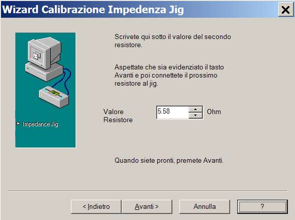
Wait for a while till the NEXT option is choosable again and substitute the first CALIBRATION RESISTOR (22.1) with the second one (5.58); again write the new value and then click on NEXT:
|
|
|
|
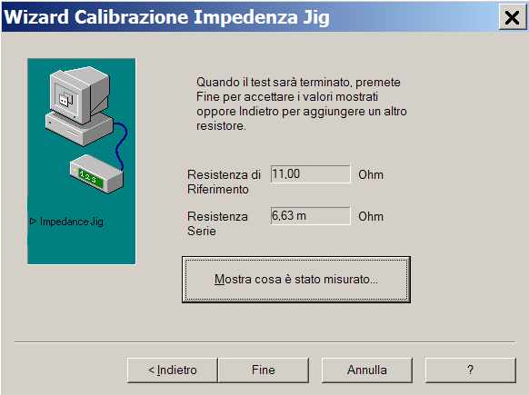
After a while a new window will appear where we can click on END :
|
|
Now in the OPTIONS & PREFERENCE click on APPLY to make the new values effective:
|
|
If you get a negative resistance, that is impossible, or a too high Series Resistance it means that something went wrong; therefore check again the cables and the inserted values and repeat the procedure.
One last click on
![]() and we are ready to test
some passive components to be sure everything is set.
and we are ready to test
some passive components to be sure everything is set.