|
|
Opening Speaker Workshop we see:
|
|
I rename the default file: MENU FILE/ SAVE AS and give a new name to the project: "TEST". To make it visible, close "SprkWk1" and open the new file: MENU FILE / OPEN/ TEST.swd .
The subdirectory "System" can't be renamed: in here are saved all the files regarding the program calibration.
|
|
We can test the sound card to see if it is compatible with SW: OPTIONS/ WIZARD/ CHECK SOUND CARD to run the soundcard checking wizard; if the result is positive we can continue. SW is not like Clio or MLSSA that have their own hardware, so it is very important to make a good calibration procedure to obtain right results; we have to discover which is the maximum volume level before the card starts distorting. We open Windows Mixer and select the menu OPTIONS/ PROPERTIES, then click on all of the little square boxes to show all of the volume controls. Click on the OK button. Check the Mute box of all control except for those marked Volume Control and Wave. Now go back and hide all but the Volume Control and Wave controls.
|
|
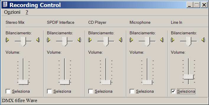
Open a second copy of Windows' Mixer and select the menu item OPTIONS/ PROPERTIES then click on the radio button Recording. This should change its name to Recording Control. Again, place a check in all of the boxes so that all of the controls are displayed. Then check only the LINE IN box.
|
|
Now hide all controls except for the LINE IN. Inspect at any Advanced controls (make the Advanced button visible by clicking on the OPTIONS/ ADVANCED menu item) and make sure that any bass or treble sliders are centered.
|
|
Open SW and click on OPTION/ PREFERENCE/ MEASUREMENT and move the cursor of Sample Rate and Sample Size all the way to the right. As a good starting point, you could use a 48k SR and a 131k SS: with these two values, we get a 24k Hz band limit (SR / 2), and a ±0.37 Hz accuracy (SR / SS), that are more than sufficient in almost any situation. In case you want to use a sample rate lower than the maximum allowed by your sound card, always use integer submultiples (96k–48k-24k). Make sure that the I/O Volume is at 100 (this value regulate the Wave volume of Windows mixer). In the GENERAL window check that the option allow 48 kHz sample rate is checked as well as the 96 kHz, if your card allows it.
|
|
|
We can close the window and we create a new folder that I called “calibrazione”; now we create a new signal RESOURCE/ NEW/ SIGNAL and call it "test"; two new files will appear, test and test.output, that we cut and copy in the "calibrazione" folder.
|
|
Now
connect the LINE OUT and LINE IN of the sound card using the LOOP CABLE (therefore
without any amplifier or voltage divider)
and set the mixer volumes to a mid-low level. On the design
tree on the left, single click on the icon ![]() so that the file name is highlighted, then right-click on it and select Properties...
from the pop-up dialog. Pick the Sine tab and make sure that the Frequency
is "1000" Hz and the Phase is set to "0" degrees;
double click on
so that the file name is highlighted, then right-click on it and select Properties...
from the pop-up dialog. Pick the Sine tab and make sure that the Frequency
is "1000" Hz and the Phase is set to "0" degrees;
double click on ![]() then SOUND/ RECORD e change the values as below:
then SOUND/ RECORD e change the values as below:
|
|
Click on ok and other 4 files will be created in the "calibrazione" folder:
|
|
Open
![]() and double click into the opened chart; in the Chart Properties window
set the X and Y axis as shown below, and we will see our first wave.
and double click into the opened chart; in the Chart Properties window
set the X and Y axis as shown below, and we will see our first wave.
|
|
|
|
|
|
|
|
Right-click
again in the chart area and select Make Chart Default. This will force
all future signals graphs of this type (time domain) to use this format. Open ![]() too, and adjust the two charts dimensions so that they fit in the desktop. Enable the VU meters in Speaker Workshop if they aren't enabled already:
go to the menu option View and make sure there is a check next to Vu
Meter. Once enabled, you will be able to read directly some statistics on
the last recording you have performed down at the lower left of the SW window.
too, and adjust the two charts dimensions so that they fit in the desktop. Enable the VU meters in Speaker Workshop if they aren't enabled already:
go to the menu option View and make sure there is a check next to Vu
Meter. Once enabled, you will be able to read directly some statistics on
the last recording you have performed down at the lower left of the SW window.
With
the "TEST" file highlighted, click on ![]() to know the clipping level of the sound card:
to know the clipping level of the sound card:
1) Set WAVE e VOLUME CONTROL to their max.
2) Set LINE IN just above its minimum, and check if there is clipping in the sinewave; if yes, it means that the Output is clipping, therefore lower the VOLUME CONTROL little by little till the clipping disappears.
3) Increase the LINE IN, till the clipping appears again; when it happens lower the LINE IN till the clipping disappears.
4) As soon as the clipping disappears, check the VuMeter and write down the value: this is the Input clipping level. It is our reference maximum level indicator, never pass its value!
5) Save the volumes settings using QUICKMIX. If you use Terratec sound cards you will not need of Quickmix, cause they already have this option in the Console.
|
This is a good wave where the Vu meter indicates a value of 27.000
|
|
|
This is a clipping wave with a value of 32.700
|
|
Now
let's record a MLS signal: for precaution, lower the
VOLUME CONTROL then
right click on ![]() then PROPERTIES/ MLS then OK; click on
then PROPERTIES/ MLS then OK; click on ![]() and set the
VOLUME CONTROL
to read, in SW VuMeter, a value between 15k-24k, but always lower then the
maximum reference level that we just found out. Once we have set it, save it as a file using QUICKMIX; it's a good
idea to save some more settings at 15k and 20k for example. If you are using an
amplifier for the impedance measurements, first regulate the amp volume to get
the desired voltage out, then set the LINE IN volume as needed.
and set the
VOLUME CONTROL
to read, in SW VuMeter, a value between 15k-24k, but always lower then the
maximum reference level that we just found out. Once we have set it, save it as a file using QUICKMIX; it's a good
idea to save some more settings at 15k and 20k for example. If you are using an
amplifier for the impedance measurements, first regulate the amp volume to get
the desired voltage out, then set the LINE IN volume as needed.
Now
we will talk about the latency. When Speaker Workshop performs a record operation it synchronizes the input and output signals using
the capabilities of Windows. This synchronization could be slightly off, depending on the speed of your computer and sound hardware
(USB cards usually have big latency). You can set the latency to adjust the synchronization to compensate for those effects. A value of 0 uses the standard synchronization. Non-zero values adjust the synch point forward and backward in
milliseconds.
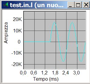
To set the value: perform a signal record operation using an wave signal in loopback mode and look at the recorded
signal "test.in.l". The wave should start at the left edge of the chart. Expand the left edge to examine the signal closely. If the signal starts before the chart begins (valid data is visible at time 0) you should try shifting the latency using negative values, perhaps –5 to start. If there is blank space and then the signal starts you should adjust the latency forward by the millisecond delay you want to introduce. A delay of <5ms is adequate and will work fine with Speaker Workshop, although you might want to tweak the delay to less than 2ms for slightly better noise results. Perform this operation a few times to make sure your computer system is consistent,
thus the delay
doesn’t vary. To change the latency values click on OPTIONS/ PREFERENCE/ DEBUG
|
Here the wave starts after 1.4 ms: there's no need to change the latency from the default value of 0 ms |
|
|
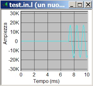
Here the wave starts after 7 ms, it's too much! We need to increase the latency |
|
|
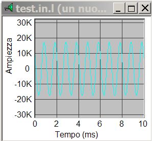
Here the wave starts before 0 ms, we need decrease latency using negative values |
|
We
can close the "Test" window and do the channel difference calibration, that
measures the differences between the soundcard inputs and adjusts for it.
Continuing using the LOOP CABLE go to the menu item OPTIONS/
CALIBRATE... and will pop up the calibration dialog; click on the
TEST button in the Channel Difference section, then the
NEXT button, and again NEXT; finally the
FINISH button when it is not grayed out. This brings you back to the
calibration dialog. Click on the OK button to close it. Now inspect
the VU meter in Speaker Workshop to check that the max reference value was not
reached. So if the inputs aren't clipping, which is a good thing, we can move on
to inspect the calibration data itself. Open the ![]() folder on the design tree, and double click on the icon
folder on the design tree, and double click on the icon ![]() .
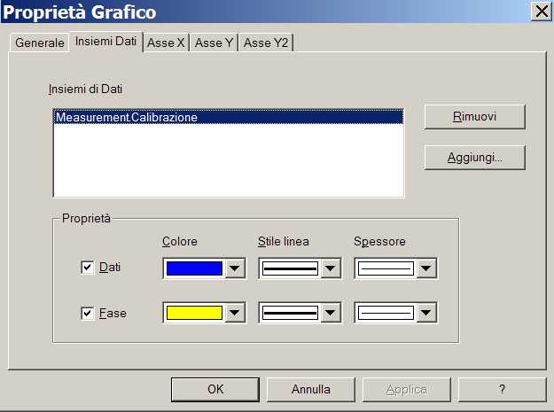
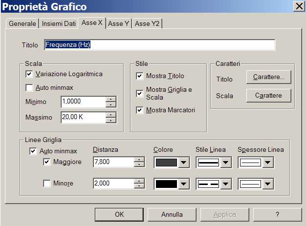
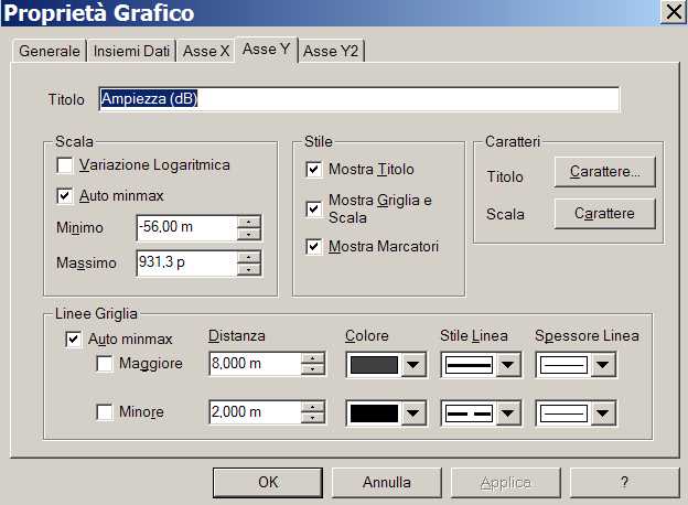
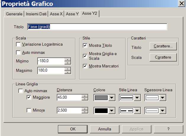
A window named "Measurement.Calibrazione" should open. To make this
graph look neater, right-click in the chart area and select Chart Properties..
and set the values as illustrated below:
.
A window named "Measurement.Calibrazione" should open. To make this
graph look neater, right-click in the chart area and select Chart Properties..
and set the values as illustrated below:
|
|
|
|
|
|
|
|
|
|
Right-click again in the chart area and select Make Chart Default. This will force all future frequency domain graphs to use this format.
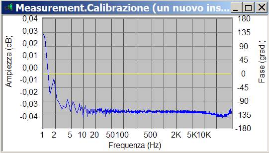
If the left and right inputs are perfectly matched, you should ideally get two straight lines at 0 dB and 0 degrees for the magnitude and phase response, respectively: the two charts below, shows what you can find. With cheap cards the problem of a not flat phase, is due by the use of a single converter: it is switched quickly between the two inputs, first doing a conversion on the left channel, then on the right, and so on, performing two conversions within a single sample period. Since the conversion for both channels isn't happening simultaneously, the 1/2 sample delay between the left and right channels shows up as an increasing phase error with frequency. Some soundcards are designed this way since a single 2x speed converter is usually cheaper than two separate 1x converters. The designer can eliminate almost half of the conversion hardware this way; however most of modern sound cards doesn't suffer of this problem. SW permits to adjust the interchannel delay: OPTIONS/ PREFERENCE/ GENERAL so that we can get a flat phase line.
An ideal situation: the magnitude (blue line) is
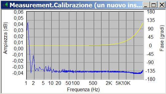
between 0.01 dB since 2 Hz; the phase (yellow line) is always flat. Here the magnitude is ok, while the phase (yellow
line) is a pain: it starts rising since 2000 Hz ! Interchannel delay
needs to be decreased.
Now it's time to check our volume settings using RIGHT MARK AUDIO ANALIZER