|
|
This article is copyright © 2006 by Audio Amateur Corporation. PO Box 876, Peterborough, NH 03458, USA. All rights reserved.
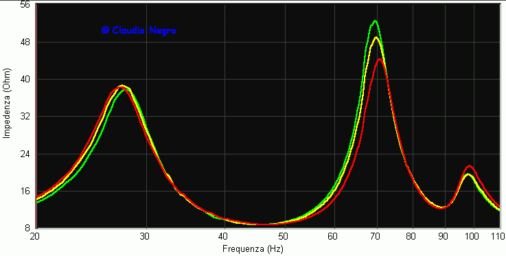
To design a double chamber system, just start by selecting a reflex alignment for the driver in use, taking into account all the known procedures to obtain a well sounding reflex system. To help you deciding, you can use one of the numerous software available; I suggest Unibox that is found in the Download folder. Then divide the total volume of the reflex (VB) so to obtain a partition that divides the box into two unequal chambers, with the bigger one the double of the smaller one; the woofer is mounted in the bigger chamber. For example if your reflex VB is 60 liters, divide it by 3 to get the smaller chamber volume (V2 =20 liters) that is multiplied by 2 to get the bigger chamber volume (V1=20x2=40 liters). As we have seen in the Impedance Comparison chart before, we can assume that FB=F2 , therefore we can go on calculating F1 and F3 using the seen formulas. But what happens when the chambers volumes are not kept in the 2:1 proportion? I investigate it by leaving the V2 volume always the same and changing V1 so to have a one liter bigger chamber and a two liters smaller one, in comparison to the ideal 2:1 volume; the DCR total volume (V1+V2) was of 35 liters. In the impedance chart below you can see the results: while the F2 is almost the same for the three curves, the F3 shows some notable differences in the two liters smaller than ideal curve.
|
|
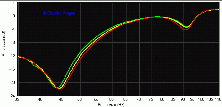
To better understand what the differences found in the
impedance chart could bring, I compared the near field responses of
the three systems; these measures were taken without adding the ports
responses since I wanted to see the systems tuning frequency (FB=F2)
given by the typical response notch. The Near Field chart confirms what we
already saw in the impedance comparison, as it should be; the three
curves show an F2 difference inside 0.8 Hz; after 70 Hz
the green and
yellow curves are similar in shape while the red
one starts falling down at 83 Hz
drawing a deeper and wider dip, for sure more audible. My
conclusion is that is better to keep the volume of V1 never
less than 2xV2 , as it can cause a more evident
typical DCR dip; even using V1 > 2xV2
(inside a 5% increase) doesn't create problems but just
a deeper F2 in comparison to the
ideal 2:1 response.
|
|
To calculate the ports
dimensions, knowing the chambers volumes and the desired F2
, just use the volume of the larger chamber (V1)
that tunes at F1 ; remember
that F2 = 1.126 x F1 therefore F1
= F2 / 1.126. Then use the founded port
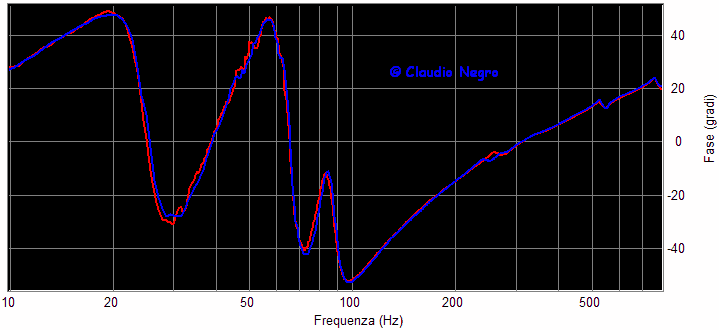
dimension for all the three ports, that are all the same. Another issue I investigate
is the position of P2 : should the tube be inside
V1 or V2 ? I measured the impedance of the DCR
once with the P2 tube inside V1
and after with it in the middle of the two
chambers: as you can see below, F2 is the same
for both the curves, meaning that the tube position is irrelevant.
However the P2 tube inside V1 phase (red)
shows more spikes, quite for sure caused by it's closer distance
to the P1 tube, therefore is better to place it in the
middle of the two chambers.
|
|
As you have seen, the design
of a DCR system is pretty easy, just pay attention at the wood cut to
get the right net volume of the two chambers. Now it's time to take a
look at Auri.