In order to work SW needs a connection between the output and the input of the sound card, and the device to test
(DUT). There are three types of connections depending on what we want to measure:
| LOOP CABLE
is used for channel calibration and for volumes setup |
|
| IMPEDANCE
CABLE is used to measure drivers impedance, to calibrate SW
and to measure passive components |
|
| ACOUSTIC MEASURE CABLE
is used to measure frequency response |
|
I
suggest to use bi-polar shielded cable, 2 x 0.75
mm, well made connectors and keep short the cables that are to be connected to
the sound card, Line In and Line Out, while there is no length problem with
the DUT cable. Be careful when soldering the minijack: remember that SW use the
left channel as REFERENCE and the right one as DATA.
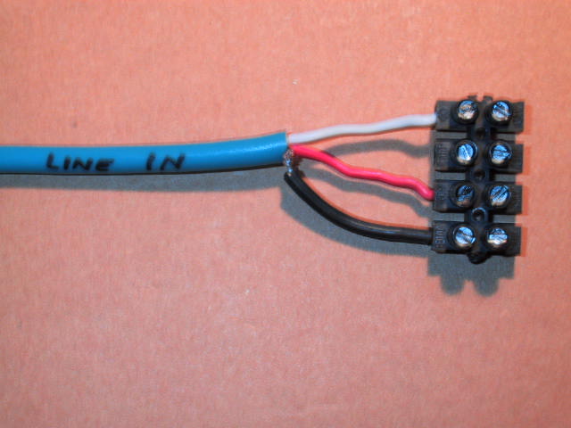
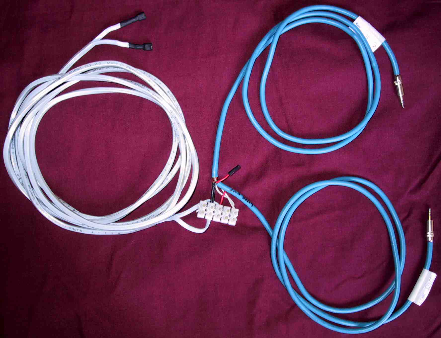
In
the following pictures the red cable is right channel; the white is the left
channel; the black is the ground while the light blue squared cable is the one
connected to the DUT.
 |
MINI JACK STEREO CONNECTIONS |
|
LINE IN CABLE |
 |
 |
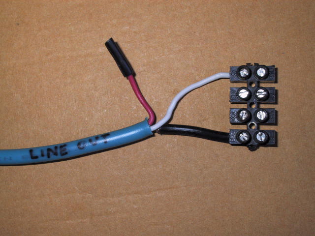
| LINE OUT CABLE |
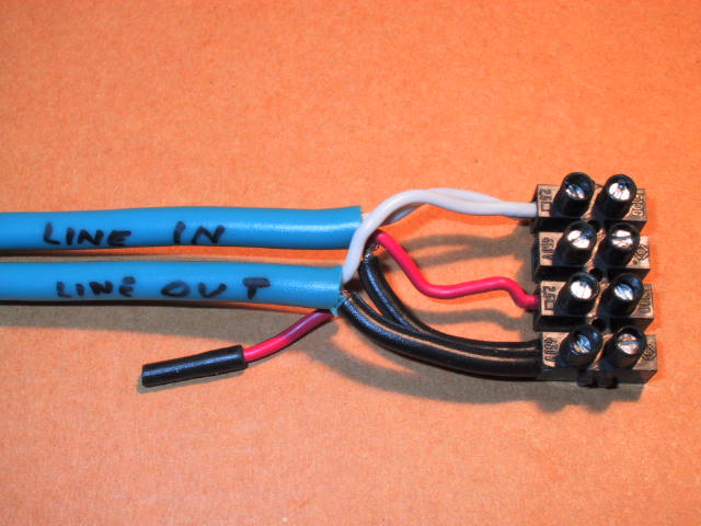
LINE IN + LINE OUT CABLES |
 |
 |
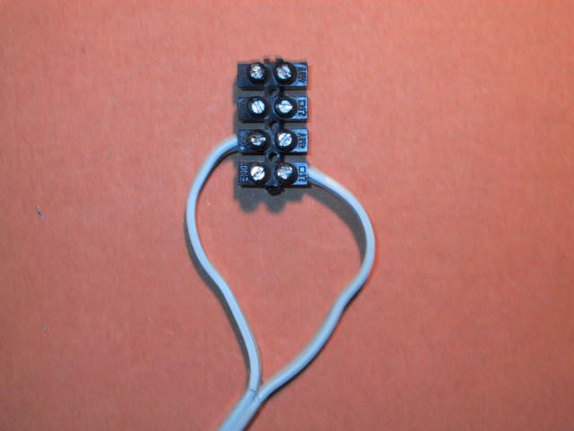
| DUT CABLE |
LINE IN + LINE OUT + DUT CABLES |
As
you can see my JIG is very easy to build and we can use it as LOOP or IMPEDANCE
CABLE just changing a piece of cable with a resistor.
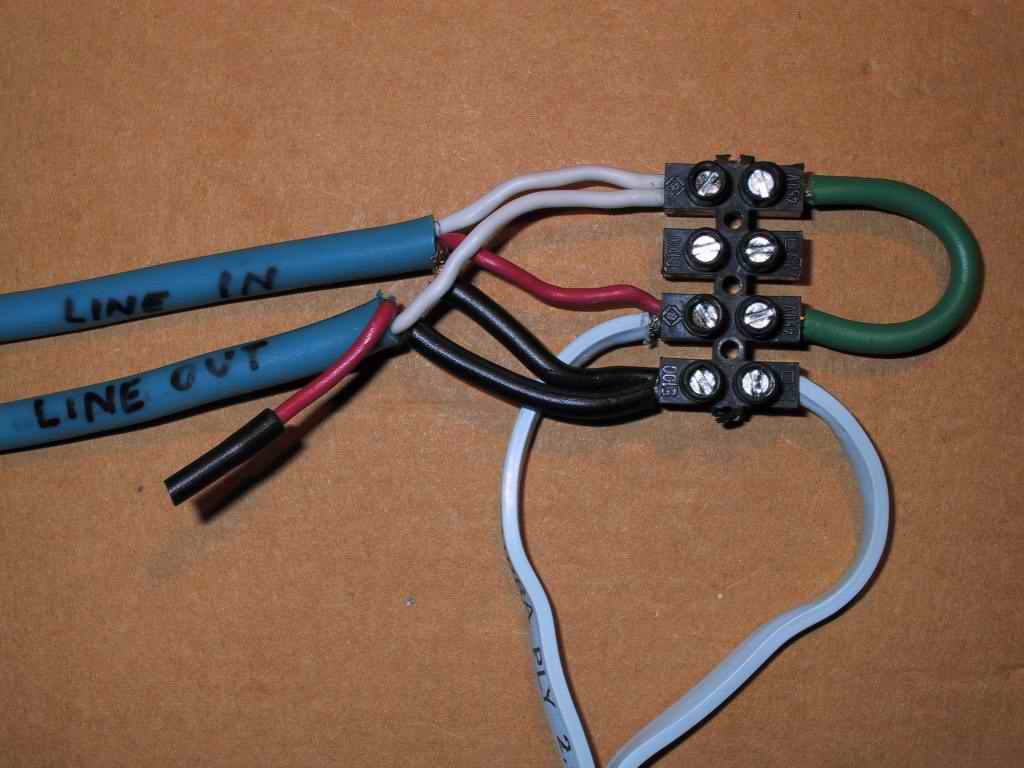 |
LOOP CABLE
Using the green cable we get a loop cable. |
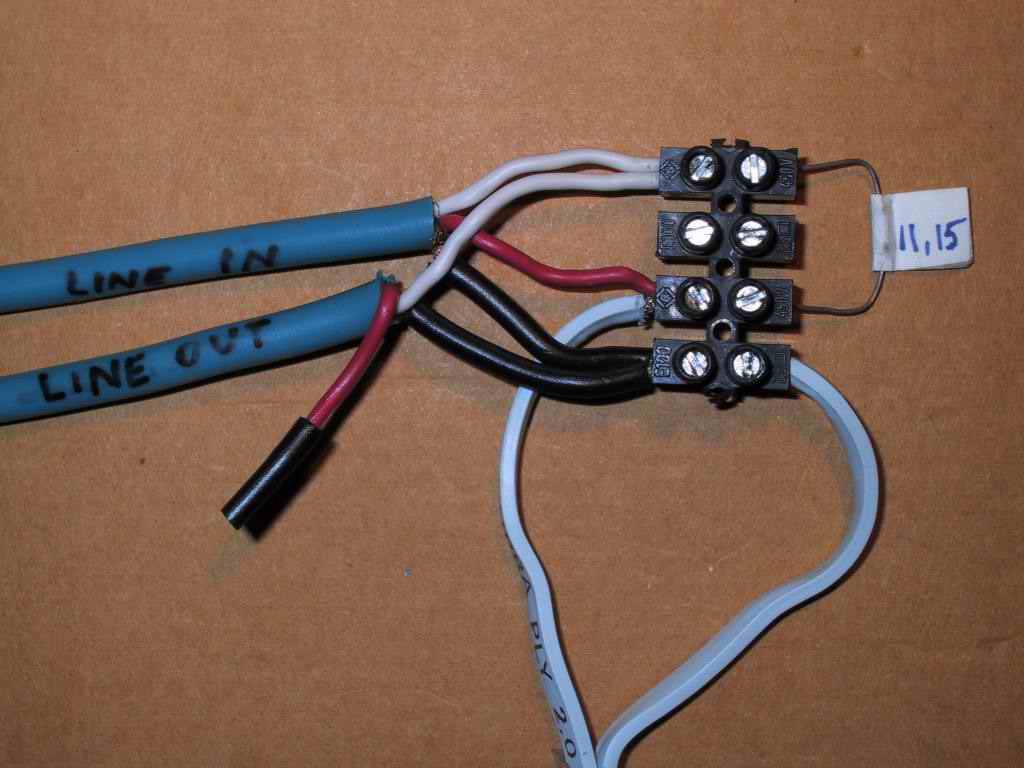 |
IMPEDANCE CABLE
This cable is used for impedance measurement and is
obtained connecting the reference resistors (11.15 ohm) |
|
|
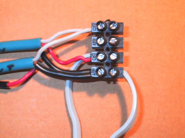
This is my JIG in Toto: the 2 blue cables
with minijack are connected to the sound card (LINE IN and LINE OUT)
while the light blue cable with two black faston is where the device
under test (DUT) is connected |
This
JIG doesn't have any voltage divider resistor so be careful: if you have an amplified
sound card you can fry it, during the volumes setup: the modern sound cards are
just pre-amplified and, usually, supports up to 1.5-2.0 volts input, so
there's no risk of
damaging them; while old SC (Sound Blaster AWE) are amplified so check it up
before connecting and be very careful during the volumes adjusting.
Pay attention at the quality of your pre-amplified
sound card: being such it means that it is intended to work with high impedance
loads and not with the typical low impedance of the drivers that we want to
measure. This can induce the SC amplification transistor or IC to work badly,
introducing distortions that would alter the measurements. In these cases you
need to add a 1000 Ohm resistor in series with the LINE OUT or you can use
an external amplifier with the knowledge of the risk of being able to burn the
SC if a voltage divider resistor is not used. An example of voltage
divider using two resistors (1k and 200) per channel is the following:
Personally, if I have to use the amplifier for the impedance measurements, I
don't use any voltage divider simply because we have to work on small signals,
thus 0.3-0.8 V are expected to come out of the ampli. Of course I pay a lot of
attention to the volume knob! When using an amplifier, just connect the SC Line
Out to the ampli Input, and the ampli Output as in the previous pic. To
prevent ground loop, you can disconnect the sound card Line In ground, but
only after you measured, with the ampli turned off, that a short exists between
the ampli Input ground and its Output negative.
If
your SC has a front module, I suggest you not to connect the LINE IN and OUT
through it but using the back connectors cause usually the front panel
connections are noisier.
Let's
go to the volumes
setup.